Dropping an FA24 into a Gen 1 BRZ went from “this seems like a reasonable way to make a bit more horsepower, reliably”, to “well, there’s no going back now” way too quickly.
I had no idea what I was getting into because apparently, nobody did. Nothing was published on the topic short of a handful of forum posts theorizing what would be needed, which struck me as odd. The FA24 has been out for two years, and several people have done this swap. The gatekeeping started feeling like a personal slight. So there was just one thing to do: buy an FA24 short block.
A brief disclaimer, I’m not an engine builder. I’ve done one engine build previously; a couple of friends and I put together an FA20 that’s currently sitting in a friend’s Scion FRS. OE build, OE everything. That was enough to give me the confidence to attempt this.
The idea was to put an FA24 short block in the car using an FA20 wiring harness and FA20 sensors. That would allow me to use the car’s factory (tuned) ECU, gauge cluster, and body harnesses. Everything should look and operate like OE while making a bunch more power. Using FA20 sensors means realistically, using FA20 everything: heads, front cover, oiling system - essentially treating the FA24 as though it were a bored-out FA20.
Why
This is a question I didn’t think I’d need to spend too much time on. I was wrong, because almost immediately after I started posting pictures of my progress online, a lot of folks questioned the wisdom of this project over, say, a K-swap.
Whether or not you came to that conclusion comes down to your goals, and your experience with cross-manufacturer swaps.
A cross-manufacturer engine swap won’t be as reliable as an OE drivetrain for a myriad of reasons. A K24 was never designed to sit longitudinally in an RWD Subaru chassis, and making it all work requires an aftermarket wiring harness, transmission adapter, oil, coolant, and fuel lines, custom engine mounts, header, and exhaust - you name it. None of which ever gets tested to the extent that an OE would, which means that swapped cars are constantly experiencing teething issues. If you’re operating a shop that’s trailering a car to and from events, that’s just part of the game. If you’re a normal person looking for years of trouble-free use, it’s a trap. Don’t believe me? Spend some time reading through the ft86 forums.
Yes, the FA24 didn’t come in the Gen 1 FRS/BRZ, so regardless I’m introducing a mountain of uncertainty. But I’m willing to bet that the amount of uncertainty introduced is significantly lower than say, re-engineering the entire drivetrain to handle a motor from a different manufacturer.
The other consideration is of course, cost and goals. I’m expecting the FA24 to cost around $7000 Canadian all-in. A complete K-swap kit from K-Power alone is around $13,000. And if you’re thinking “Well, a K24 can make 450whp when boosted”, that’s where goals come in.
I had the most fun with my FRS when it was tuned on E85. We never dyno’d the car, but I suspect it made around 190whp. If I’m able to make the 220whp that stock Gen 2 cars have been making, without the hassle of carrying around ethanol to events, I'll consider this a huge success.
If dropping $7000 to gain ~30whp and some convenience sounds crazy, the car needed a motor anyways because I had the wisdom to buy the worst BRZ on the planet.
Looking for problems
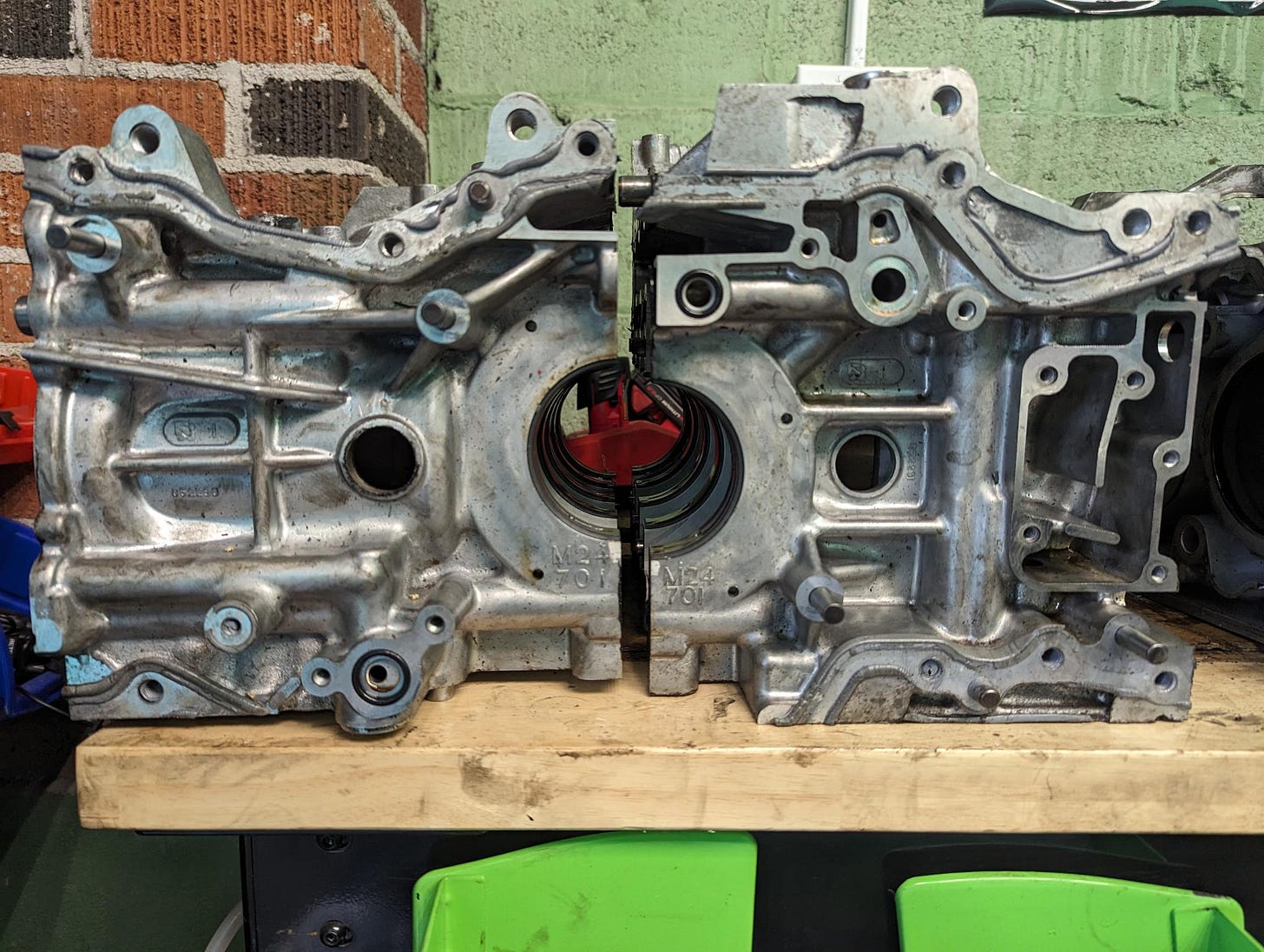
You’ve heard this story before; an enthusiast buys a BRZ, takes it to the track, and eventually spins a rod bearing. Subaru denies their warranty, and they’re left on their own. It happened to one of my fellow time-attack competitors. I stepped in and purchased their damaged FA24 for the price of their core charge, brought it home and placed it on a workbench next to the (also broken) FA20 short block that came out of my 2015 BRZ. If the goal was to mount FA20 heads and accessories to this FA24, I had to start by identifying every difference between the two blocks.
The first and most obvious difference between these two engines is actually their connecting rods. Subaru opted to use symmetrical connecting rods on the FA24 as opposed to the asymmetrical connecting rods found in the FA20. This means the connecting rods need to be bolted to the crankshaft first, and then the entire rotating assembly is installed in the block. Pistons are installed after, and the wrist pin is inserted through holes in the cylinder walls.
If you’re building your own FA24 bottom end, that makes assembling the bottom end easily twice as tedious as an FA20. If you’re not, you’ll still need to be mindful of these holes in the cylinder walls - more on that later.
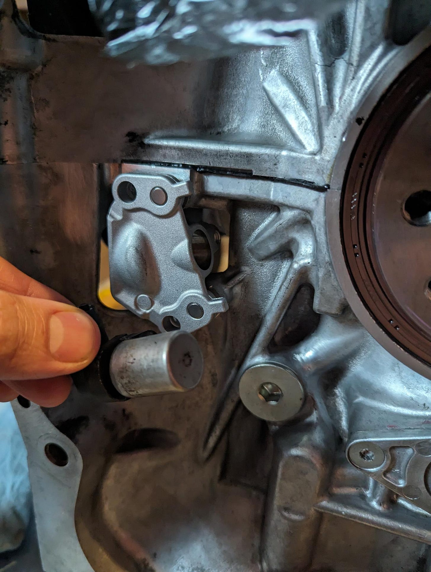
The second thing is seemingly minor but insanely consequential: the crank position sensor. I only had an FA24 short block - nothing more. So I could tell that the FA20 crank position sensor holder didn’t quite fit on the FA24 (one bolt hole lined up, the other didn’t), but I didn’t (and still don’t) know what the FA24 crank position sensor and reluctor wheel looks like. Optimistically, I ordered an FA24 crank position sensor holder in the hope that that would allow me to use an FA20 crank position sensor without making any changes, and crossed my fingers.
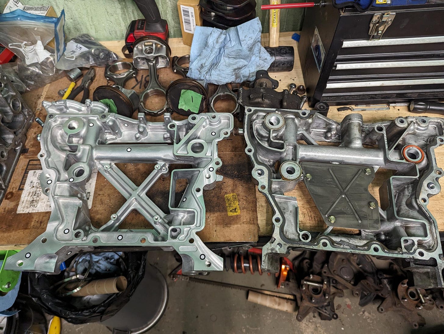
A friend of mine happened to have access to a brand new FA24 upper pan, because he’s been working on a project to solve the FA24’s factory oiling problems. That allowed me to compare the two oiling systems and mounting points, which is when I noticed a significant difference between engine mounts across the two engines.

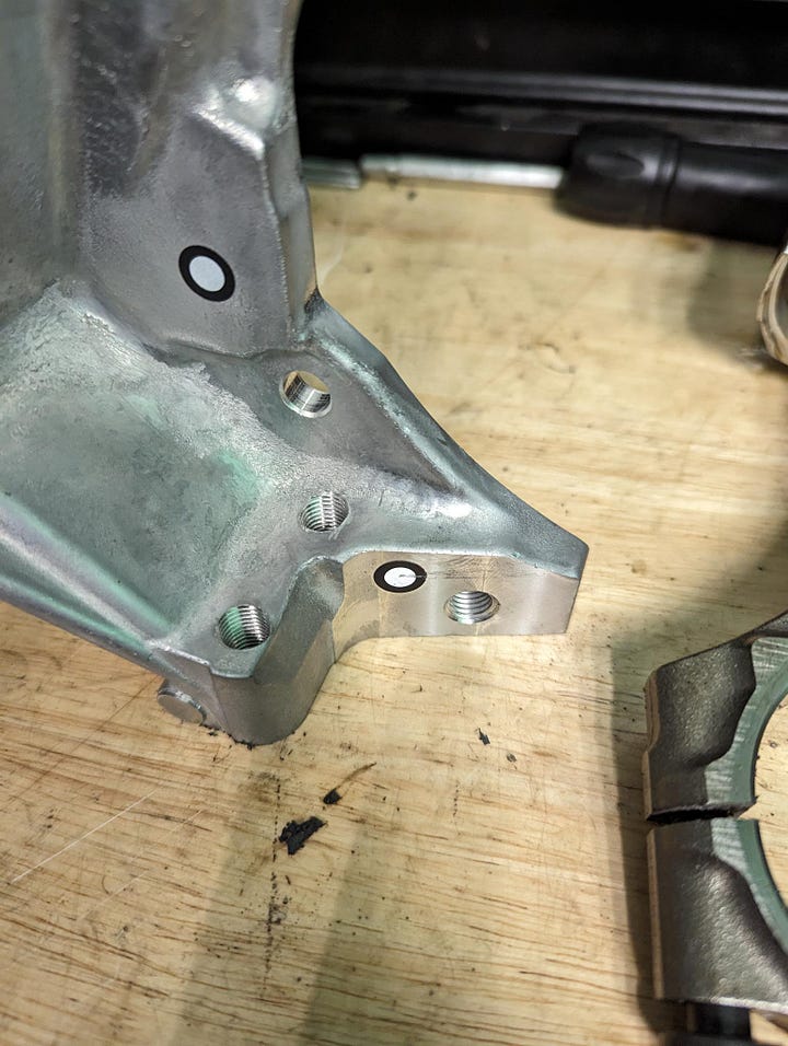
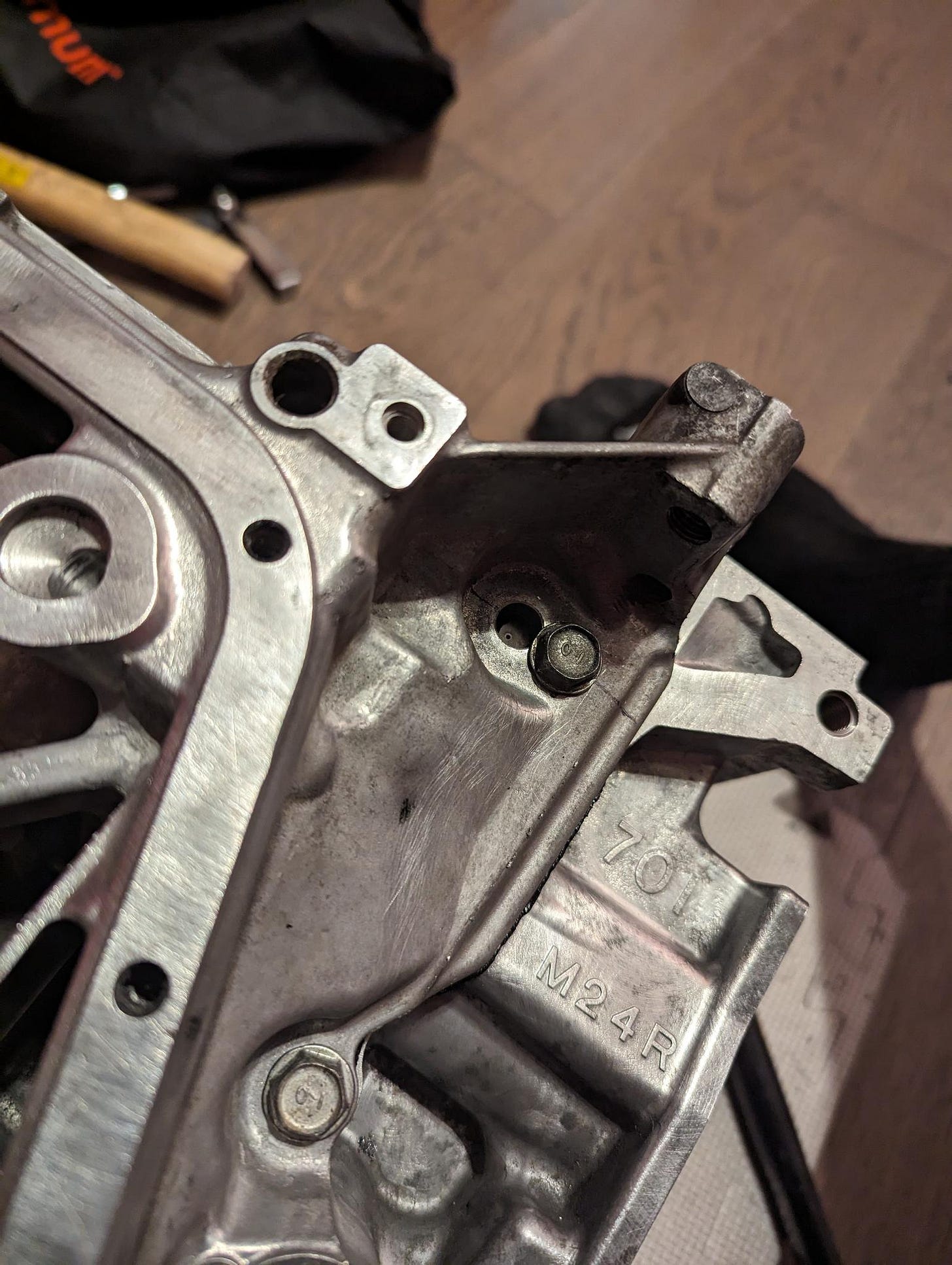
The FA20’s engine mounts connect to the engine using two bolt holes: one on the upper oil pan, and one on the block itself. The FA24’s engine mounts connect to the upper oil pan. Combine an FA24 short block with an FA20 upper oil pan, and well, you’re only left with a single bolt hole for your engine mounts.
Luckily, the upper pans are identical in all the ways that matter. The mating surface between the FA20 and FA24 upper pans are the same (ignoring one pesky bolt hole), and the oiling passages between the upper pan and block were the same in terms of position and o-ring diameter.
Then there’s the big one - mating FA20 heads to an FA24 block. I started by placing an FA20 cylinder head on an FA24 at top-dead-center, and to virtually nobody’s surprise, the piston contacted the head. At 12.5:1 compression both the FA20 and FA24 have pistons that exceed the block’s deck. With a much smaller bore, the side of the FA20 heads were smacking into the piston, lifting them by about 0.8mm.
So for those keeping track at home, we have:
Engine mounts that no longer fit
A misaligned bolt hole on the FA20 upper pan
An FA20 crank position sensor that doesn’t fit on the FA24
FA20 heads that don’t fit on an FA24
The good news is that everything else looked fine. The front cover should have no issue bolting up (all FA20 tensioners and guides fit without issue), the heads bolted up (minus our piston-clearance troubles), the upper pan mostly lined up, the bolt holes on the crankshaft have the same orientation relative to the key on the crank nose, and little things like knock sensors bolted up just fine.
Engine Mounts
I thought the inability to bolt engine mounts to my FA20/24 hybrid engine would be my greatest challenge - largely because we would need to either add a bolt hole to the block or weld on new material.
That begs an obvious question: why not use an FA24 pan, and avoid this whole mess? I wanted to use an FA20 upper pan for two reasons. There seems to be a generally accepted consensus that the FA20 is better at managing oil pressure than the FA24, and there are noticeable differences between the two pans, namely, the passages that carry oil from the left head back into the oil pan.

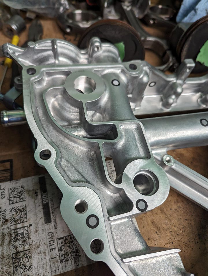
I’m not an engineer, and the folks who made these decisions are, but given the FA24’s reputation for losing oil pressure, I’d rather keep this engine as FA20 as possible.
Then comes the compatibility issues that an FA24 upper oil pan would introduce. An FA24 upper pan means using an FA24 oil pickup tube and oil pan, which would need to be compatible with an FA20 front cover. The FA24 oil pickup meets the front cover in the same place, with an identical o-ring, but it protrudes 10mm further outwards into the front cover, meaning that the FA24 uses a different oil pump.
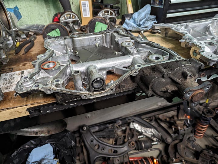
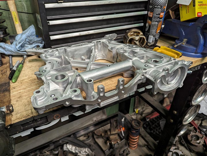
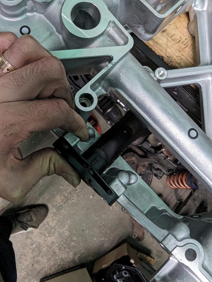
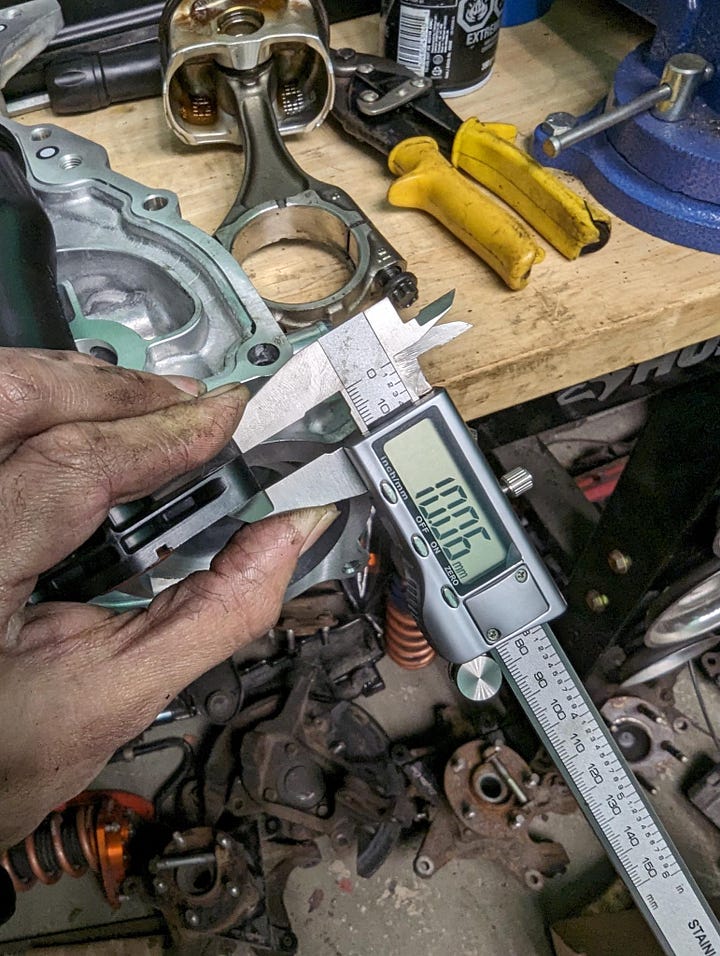
So I had two choices: use an FA24 upper oil pan and solve the oil pump compatibility issue, or use an FA20 upper pan and solve the engine mount issue. A failing engine mount means calling a tow truck. A failing oil pump means losing your motor. I needed to make engine mounts work with an FA20 upper oil pan.
For this, I reached out to the best aluminum fabricator I know; Vinh from NV Auto, who pretty quickly deduced that some sort of custom engine mount would be needed.
As much as I wanted to retain usage of the OEM-style STi engine mounts, I had to concede for one simple reason: they’re made of plastic, and thus can’t be cut and welded. Luckily my BRZ came with Cusco mounts that feature a replaceable bushing and a steel frame. Vinh chopped them, welded a section that sits flat against the block, and drilled and tapped a hole in the corner of the FA24 block.
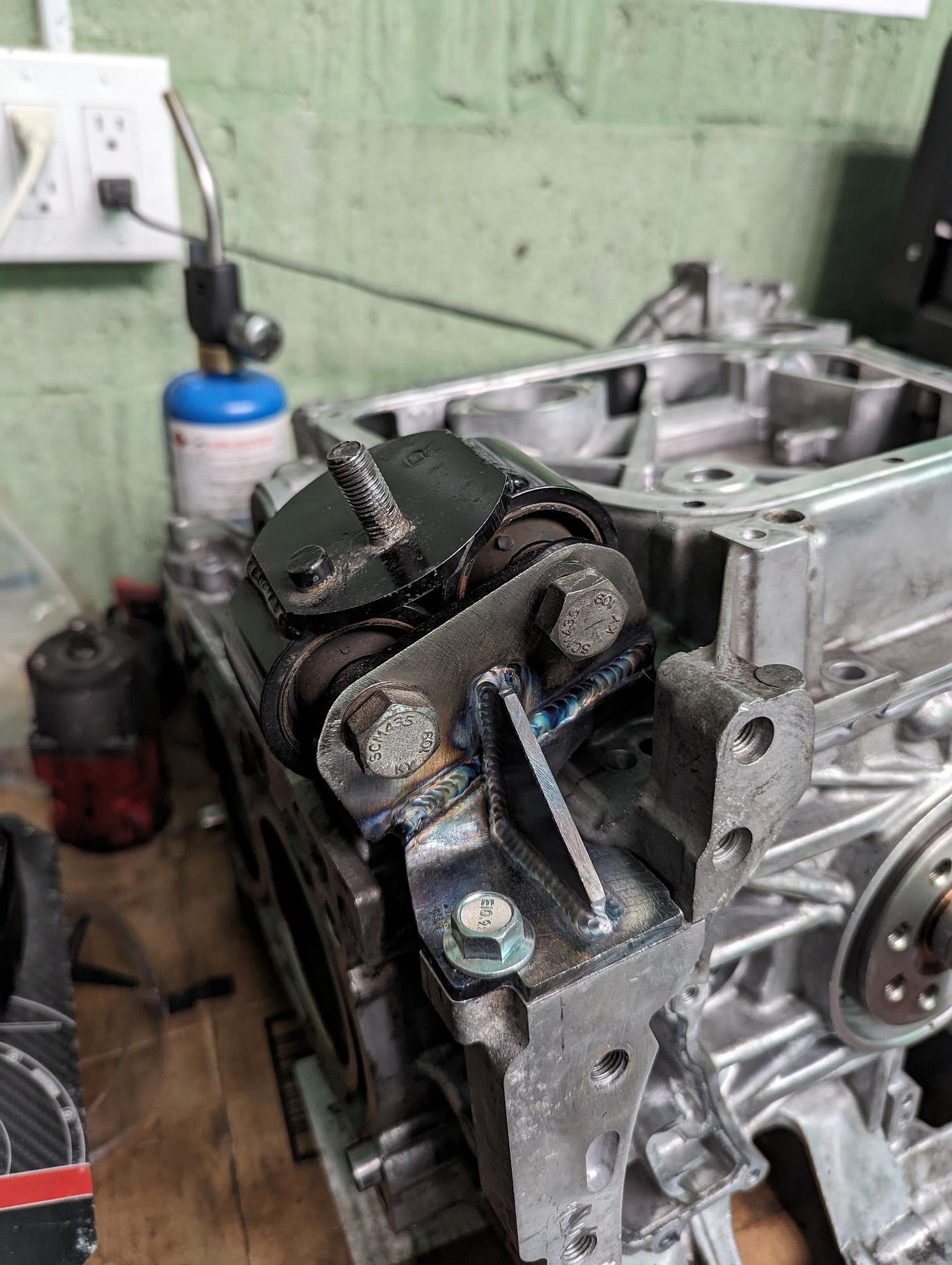
He was also kind enough to drill a hole in the upper oil pan, to account for the one bolt hole on the FA20 pan that didn’t line up with the FA24 block.
Crank Position Woes
From everything I’ve read online, this appears to be the one thing nobody can figure out. Or at least, that nobody cares to explain. I’ve learned not to take forums too seriously; the days of people pouring their brains and expertise out online appear to be over, so I figured there was probably a simple solution that nobody was talking about. After all, I’m not the first person to build an FA24 in this manner.
I started by ordering an FA24 crank position sensor holder online. Idiotic in retrospect, but the hope was that the FA24 CPS (crank position sensor) holder would simply accommodate an FA20 sensor. That ended up being very much not the case; it turns out the FA24 sensor is both a different diameter, and is orientated in a different direction than the FA20 sensor. So I started by just making the FA20 sensor holder fit on the FA24 block - which was a fairly simple ordeal.
I know, vertical videos, I’m sorry.
The two dowels on the FA20 sensor holder line up perfectly on the FA24. The top of the holder does contact the block, but trimming the top of the holder with a Dremel solved that. Only one bolt hole lined up, but I elected to not solve that. A single bolt combined with the two dowels should be sufficient to support the sensor.
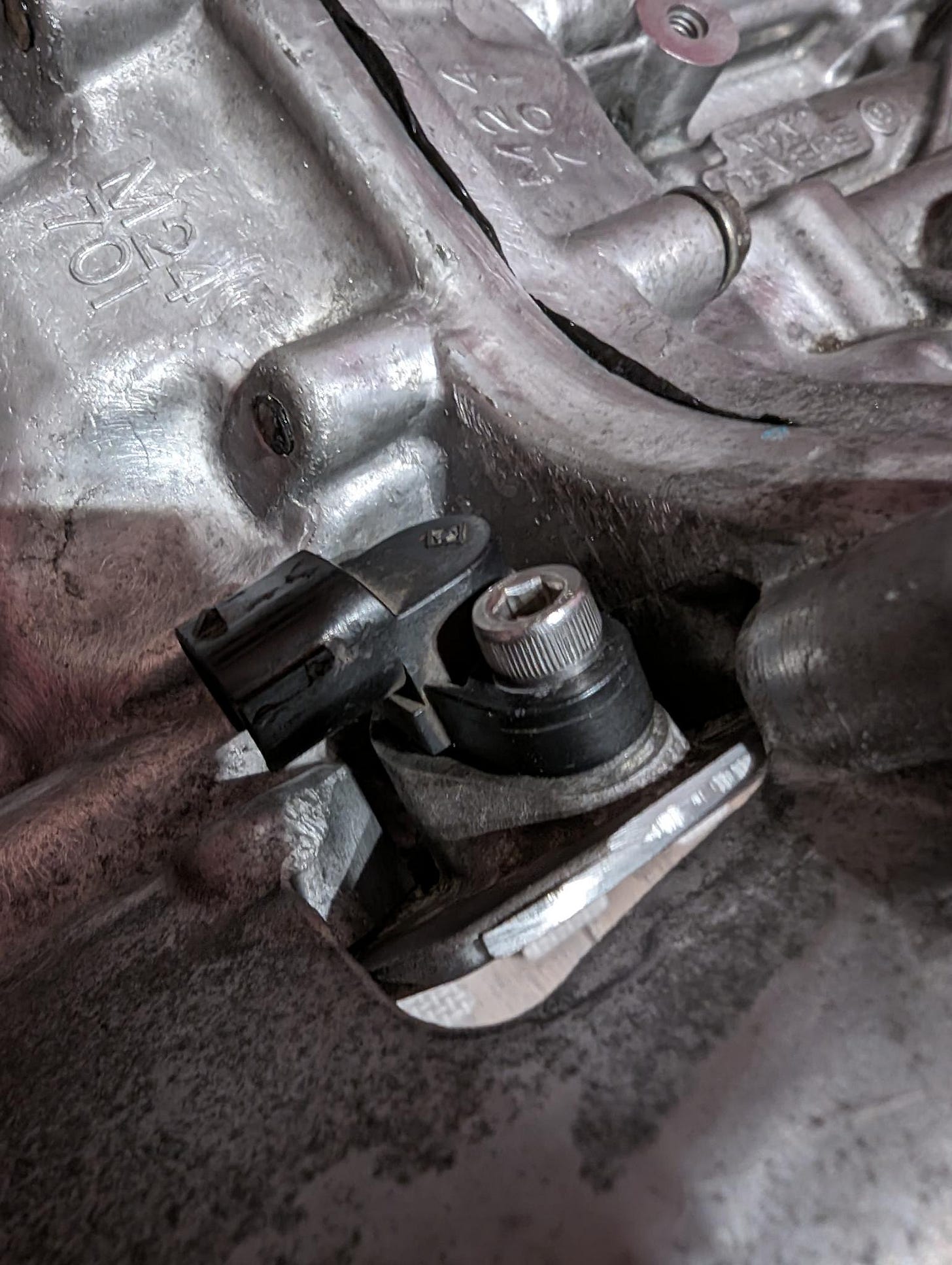
With the sensor now installed, placed the FA20’s reluctor wheel on the back of the engine, and it contacted… Well, everything.
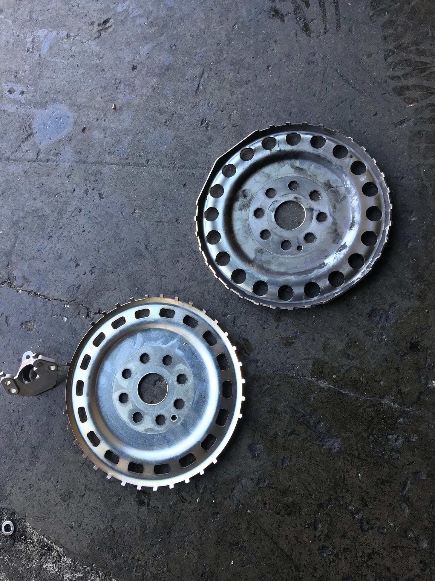
I haven’t been able to find a picture of the FA24 reluctor wheel, but I can safely assume that it’s both smaller (in terms of diameter), and flatter than the 13-16 FA20’s. Bolting an ‘13-’16 FA20 reluctor wheel to an FA24 leads to it contacting both the inspection cover (on the left in my last video), and opening on the right that allows for the insertion of piston wrist-pins. Dealing with the inspection cover was the easy bit; some lightwork with a Dremel was all that was needed to allow it to clear. The right side was what kept me up at night.
I swear I’m almost done with the vertical videos.
I determined that I would need to remove about 0.220’ of material from the block and figure out an alternative way to seal the wristpin passageway, for the reluctor wheel to clear. Which is, a lot. Going too deep means putting a hole in the cylinder itself. There are two ways to think about this. Either you have to:
Use a smaller reluctor wheel, or reposition it
Remove block material, and seal the wrist pin passage.
The ideal solution is to use a smaller reluctor wheel. I wasn’t able to confirm this, but the ‘17-’21 reluctor wheel looks like it’s small and flat enough to sit on an FA24 without issue. Unfortunately, I can’t find anybody who’s managed to use +2017 sensors in a 2013-2016 car. And sure, with an aftermarket harness and ECU anything is possible, but if that’s the approach you’re going to take, you may as well start with a complete FA24 engine and harness.
I went down this rabbit hole deep enough to consider things like mounting the reluctor wheel to the crank pulley, a common thing to do on some older LS swaps, with a custom crank position sensor bracket, but abandoned that quickly because it would introduce a lot of uncertainty (what if you can’t get the reluctor wheel perfectly centered? What if you don’t get the timing right? What if the reluctor wheel damages the accessory belt?).
If I removed enough block material to allow the ‘13-’16 reluctor wheel to clear, I would be left with 0.270” of material between the inside of the cylinder. This is really important, because the piston slightly overlaps this hole at the bottom of the stroke. If you plug the hole, whatever plug
you use cannot protrude into the cylinder. This didn’t seem like enough material for an NPT plug to seat correctly so I landed on an exceedingly simple solution: a 25mm expansion plug.
This isn’t the most serviceable solution, and expansion plugs are notoriously difficult to get right, so this solution is a bit of a leap of faith. Time will tell.


It’s at this point that I need to introduce Kyle. He’s a friend of a friend, the owner of a TDI-swapped Porsche Boxster, and an excellent CNC machinist. I originally visited him to sort out my cylinder-head-clearance issues (more on that later), but he was able to carefully carve enough material out of the cylinder block to let the reluctor wheel to clear.
From there, I coated the plug and passageway with a thin film of RTV, and carefully tapped the expansion plug into place with a socket on an extension and a hammer. I was able to inspect the inside of the cylinder with the upper oil pan off, and ensure that the expansion plug didn’t protrude into the cylinder.
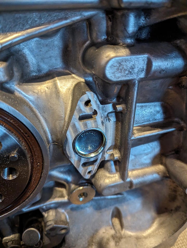
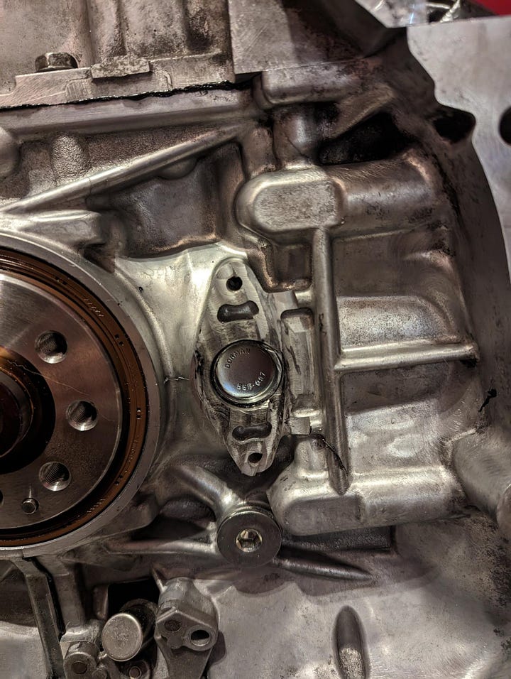
A couple of lessons here. We tried to leave as much material on the block as possible, but this meant that the “entrance” of the passageway was higher on one side than the other. Expansion plugs deform when they’re installed, so this meant that the expansion plug would have deformed unevenly leading to leaks.
To deal with this, I needed to sand the left side of the passageway’s entrance with a Dremel just enough to insert the expansion plug evenly. If you’re planning on doing this, I would either insert the expansion plug before CNC’ing the block, or machine the surface flat so that the entire entrance of the passageway is even.
Once all that was done, the reluctor wheel cleared the block but it hit the crank position sensor itself. Luckily this fix was simple. I setup an FA20 on a bench with a crank position sensor, and using feeler gauges, I determined that the FA20’s reluctor wheel clears the crank position sensor by 0.65-0.70mm. From there, I shimmed the crank position sensor (as it sits on the FA24) using a washer that was lightly ground down until its clearance matched that of the FA20.
Head Work
Making FA20 heads fit on an FA24 was by far, the most intimidating part of this build. There were two problems to tackle:
Having the pistons clear the heads
Solving for a new compression ratio
Getting the pistons to clear the heads was the simple part, but it required more help from my CNC operator friend Kyle. I started by placing an FA20 head on an FA24 at top-dead-center, and determined that the piston lifted the head by 0.80mm. We solved for this by chamber-cutting the heads to expand the combustion chamber’s diameter from 86mm to 94mm.
The goal was to get the heads to clear the pistons without the head gasket. Since the head gasket is 0.6mm thick, that would result in a minimum head-to-piston clearance of more than 0.6mm. Cut, place the head on the block, and see if it clears. Rinse and repeat until you get it right.
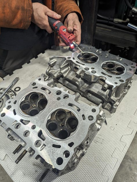
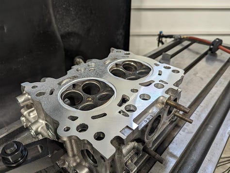
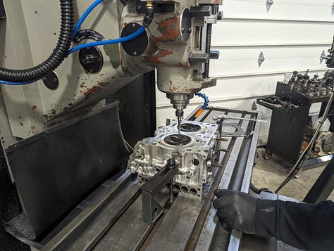
What helped during this process, was placing a coating of permanent marker on the pistons. Contact between the head the piston would show up on the marker, indicating where we needed to cut. We ended up cutting a ring with a total depth of 0.11mm, and hand-grinding the side of the head slightly (as pictured above). The end result was surprisingly clean and dare I say, professional.
Math
Then came.. math.
Because when you swap heads - especially heads with a combustion chamber that’s 8mm narrower, you’re going to change the compression ratio in unexpected ways. Figuring out what the new combustion ratio will meant a bunch of math, and a bunch of measuring.
First, you need to figure out the target combustion chamber size, based on a stock FA24’s compression ratio.
CR = Swept Volume + Clearance Volume / Clearance Volume

12.5:1 = 596.82cm3 + Vcl / Vcl

12.5Vcl = 596.82cm3 + Vcl

12.5Vcl - Vcl = 596.83cm3

Vcl = 51.9cm3
In other words, to achieve an OE compression ratio I needed 51.9cm3 of volume between the top of the piston (at top dead center) and the heads. That area can be broken out into two sections:
Piston (i.e., the volume fits in the piston at TDC)
Headgasket
Cylinder head
Piston volume is something that you can usually Google. Unfortunately, this engine hasn’t been around long enough (as far as I can tell) for something so niche to get published.
You can measure piston volume using oil and a laboratory burette, similar to the process usually followed to measure cylinder head volume:
Turn the crank so that the entire piston is below the deck
Measure how far down in cylinder the piston is sitting
Cover the perimeter of the cylinder in grease, and place a heavy piece of plexiglass with a hole in it, over top.
Using a laboratory burette, fill the cylinder completely with engine oil.
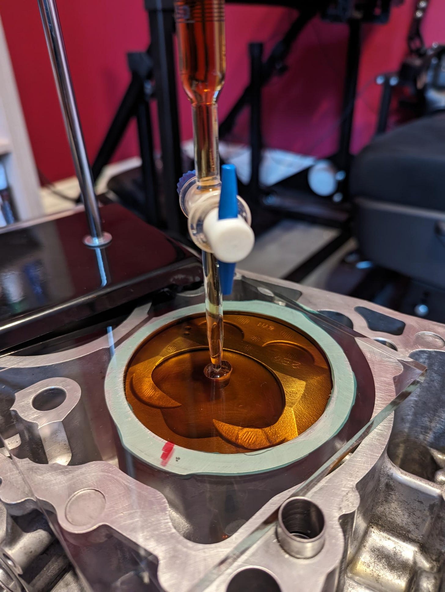
There are a million videos on Youtube that explain this process that I have. The basis is, that filling the cylinder with oil will tell you the volume of the cylinder. Use math to figure out the mathematical volume of the cylinder. Subtract actual from theoretical, and you get the amount of volume, in the piston.
Measured Volume = 45.4cm3

Piston Depth = 5.84mm

Mathematical Volume = π(r^2)h
Mathematical Volume = 3.14(47mm^2)5.84mm
Mathematical Volume = 40528mm3 or 40.5cm3

Piston volume = 45.4cm3 - 40.5cm3
Piston volume = 4.9cm3
I managed to fill my cylinder with 45.4ml of oil - and I did this twice to ensure consistency. Math gave me a theoretical piston volume of 40.5ml, so in theory, 4.9cm3 was hiding in the piston.
This process was super messy and had a significant margin of error. Determining the theoretical volume meant using a caliper to measure piston height. Being off by just 0.1mm meant a difference in piston volume of 0.7cm3: huge. So while I’m using this number, it’s an imperfect measurement. I took three different measurements with a total deviation of about 0.2mm; so my margin of error is 1.4cm3
Determining the volume taken up by the head gasket just took some math:
= π(r^2)h

= (3.14)(47mm^2)(0.6mm)

= 4.16cm3
Then came the messiest part; measuring cylinder head volume. I used the same setup used to measure piston volume: a plexiglass plate over the cylinder head, a burette filled with oil, and some grease to seal the plexiglass against the head.
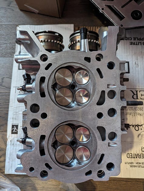
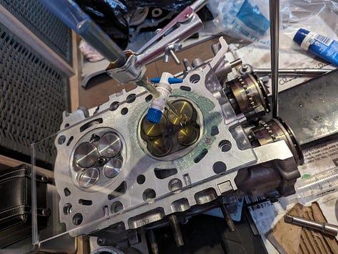

I did this a few times and my most consistent measurement was 44.3ml. This isn’t a number that makes sense to me. The published FA20 cylinder head volume is 37.6ml. The CNC cut we did to extend the cylinder bore should have, by my math, only added 1.5cc3 of volume. Add in the light grinding we did after the initial cut, and my new cylinder head volume shouldn’t exceed 40cc3. And this was after repeating the process three separate times.
There are lots of reasons this could happen. The main one; oil leaking out of the valves, spark plug hole, DI injector holes, or all of the above, throwing off my measurements.
All of this leads to the following conclusion. The combustion chamber is anywhere from 47.66cm3 and 53.36cm3 (the former if I got things wrong, the latter if I got the math and measurements right)
That means that my compression ratio is somewhere between 12.2:1 and 13.5:1. Which is to say, it should make good NA power and should be safe on high-octane fuel. I hope.
Assembly & First Start
Once I figured out all of the above, there was no magic involved in assembling the motor and dropping it in the car. I mated the FA20 upper oil pan to the block being mindful to seal the additional hole we added with RTV, and installed the OE pick-up and oil pan.

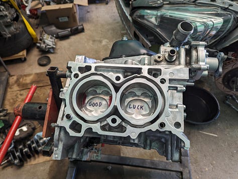
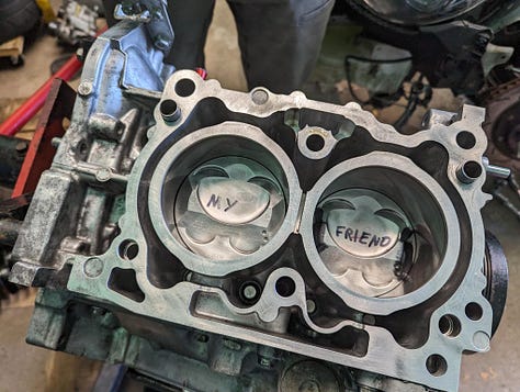
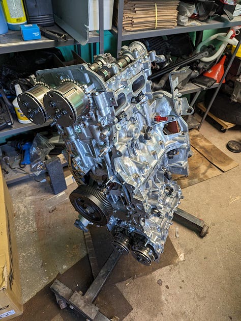
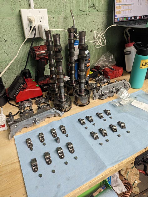
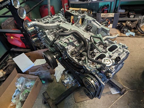
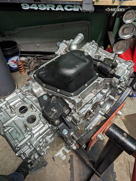
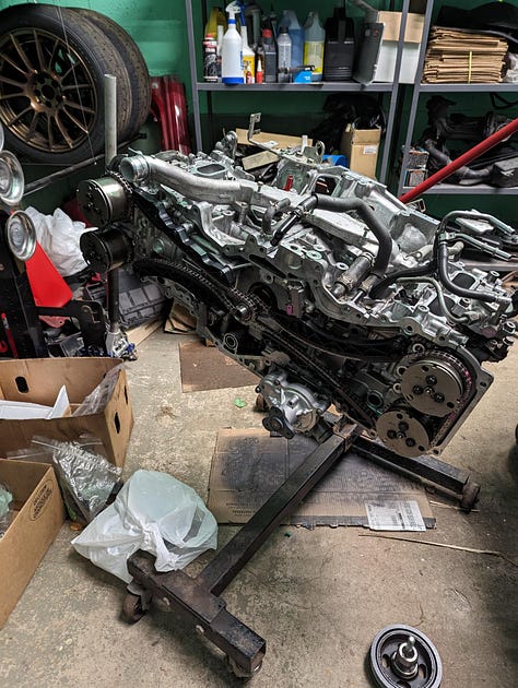
My freshly machined FA20 heads, complete with new GSC valves and 8200rpm valve springs, bolted to the FA24 without issue. I turned the engine over a ridiculous number of times looking for interference issues. From there, I shimmed the valves using new valve shims from Subaru, and installed the front cover, intake manifold, wiring harness, etc.
In other words, I assembled the engine like you would any other FA20.
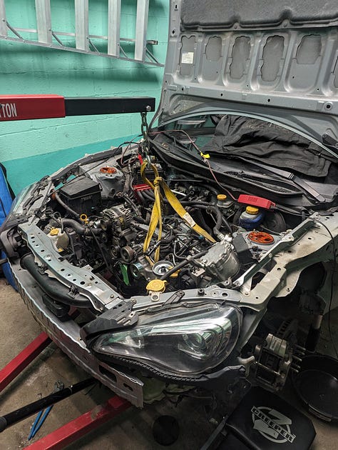
From there, I lowered it into the chassis, attached all accessories and bolted up the transmission. Again, like any other FA20. From there, I turned it over until I saw oil pressure, and added fuel, and it started on my first try.
Obviously, everyone wants a dyno number, as do I. That’ll need to come in a Part 2, because as of this writing, I’m currently in bodywork hell and have a long way to go until this is a truly functional car.
Cheers everyone,
Phill





I haven't finished reading this yet but before I forget thank you so much for this write up. The gatekeeping was crazy.
Hey this is amazing work its impossible to find others records of this! I have two questions though:
1. Does the FA20 lower oil pan fit on the FA24 upper oil pan (I have modifications done to it for my Turbo's return line) or would I need to use the FA24 lower oil pan if I am using the FA24 upper oil pan?
2. Why didn't you a spacer (maybe washers) between the crank position sensor and the crankshaft so the pins on the reluctor wheel would clear the plug. From the video it seems like it was only hitting by a few centimeters. Do u think such a tiny increase in space would affect the clutch?
Thanks.